Last Updated on May 13, 2025 by Eric C. Hamdan

**The latest project repository is here!**
This article is Part 1 of a series. The other parts can be found here:
- Part 2: Simulation
- Part 3: Wrapper, Implementation, and Testing
Table of Contents
Introduction
Like many FPGA beginners, one of my first tutorials was the classic “turn on an LED” project. While a great starting point, I wanted to explore further. I also found the LED far too bright! This led me to design an LED “dimmer” using Pulse Width Modulation (PWM). With PWM, we can lower each channel’s brightness. PWM also allows color mixing in RGB (three-channel) LEDs.
In this project, we’ll parameterize the PWM output using VHDL generics. We’ll keep it basic and set the brightness and color at compile time, keeping them static at runtime. We’ll deploy the LED dimmer design to the Arty A7 board (featuring the Xilinx Artix-7 FPGA) and utilize an onboard switch to turn one of the three-channel LEDs on and off.
The short journey to creating and deploying our module spans three parts:
Part 1: VHDL Design
- Understand PWM in our context.
- Design the LED dimmer and code it in VHDL.
- Module verification with a self-checking test bench.
Part 3: Implementation and Test
- Create a top module wrapper for the Arty board.
- Synthesis, Implementation, and Timing Analysis.
- Programming the hardware and enjoying the results.
Let’s dive into Part 1!
Why Pulse Width Modulation?
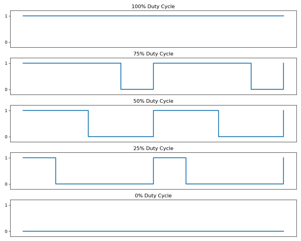
PWM is a technique that uses rectangular pulses of varying durations and spacings to emulate a continuous signal or transfer information. So, what does this have to do with LED brightness? In digital systems, supplying a HIGH value (binary ‘1’) to the LED output results in full brightness—100%. But how do we achieve brightness levels between 0% and 100%? Instead, we can periodically switch the output between HIGH and LOW—a train of rectangular pulses. When this switching occurs at a sufficiently high frequency (typically tens or hundreds of kilohertz), the LED appears dimmer, without flicker to the human eye. The average power delivered to the LED decreases as the time spent in the HIGH state, known as the duty cycle, decreases relative to the total PWM period.
The duty cycle is expressed as a percentage from 0% to 100%:
- 100% duty cycle: The signal is always HIGH, delivering full power.
- 50% duty cycle: The signal is HIGH for half the time, delivering half power.
- 0% duty cycle: The signal is always LOW, delivering no power.
We represent the duty cycle using integers 0 to 1000 (inclusive). This allows a 0.1% granularity in duty cycles, for example, 27.2% is permissible (and enough for this application). We could allow for user-specified scaling, but “hardcoding” the scaling permits us to use ranges in our duty cycle generics, which improves robustness against invalid values during synthesis.
In summary, PWM is ideal for LED dimming because it’s a way to lower the brightness that is easily implemented on a digital system. If the LED is three-channel, PWM can also enable color mixing!
LED Dimmer – Block Diagram
Okay, now that we better understand PWM, let’s outline our module. We want to make a module that outputs three PWM channels to our LED. We’ll need an input for the input clock, which drives our PWM process and synchronizes everything. We’ll include a reset signal input and add an input for an enable switch, which provides input for the physical ON/OFF switch on the Arty.
IMPORTANT: We’re making a fully synchronous design; the reset and enable signals are synchronized to the input clock.
Let’s make a block diagram.
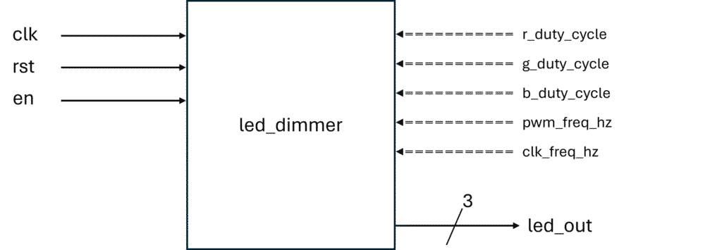
The inputs to our module are:
clk— Input clockrst— External reset signal (active high)en— PWM enable (high starts and low stops the PWM output)
The single output is:
led_out— PWM signals (3-bit width)
I’ve included generics as well (denoted by the left-facing dashed arrows):
r_duty_cycle— Red duty cycle, integer [0, 1000]g_duty_cycle— Green duty cycle, integer [0, 1000]b_duty_cycle— Blue duty cycle, integer [0, 1000]pwm_frew_hz— PWM switching frequency in Hzclk_freq_hz— Input clock frequency in Hz
These generics allow us to set the duty cycles for the RGB channels individually and specify the input and PWM clock frequencies so that the internal counter counts correctly.
This block diagram helps us conceptually and perfectly outlines the VHDL entity we are about to write.
PWM Counter Outline
Let’s figure out how to generate the PWM signals. We want three PWM outputs that act concurrently, but once we solve the problem for one, we’ve got it. We also want to support a range of input clock and PWM switching frequencies in our design. Also, we’ll choose a synchronous design. Before we dive into the code, let’s write out the overall process:
For each rising edge of the input clock:
- If
rstis high, then output zeros and reset the counters - Else if the enable signal is low, we still output zeros, yet leave the counters as they were
- Else, let the counters run and output the PWM signals for each channel.
Let’s break this down further. If the external reset is asserted, we output LOW on all channels and set the counters to zero. If the external reset is deasserted but the enable is deasserted, we still output zeros but leave the counters with the last value they had (allowing us to restart where we left off). Finally, the else clause captures the event when the reset is deasserted and the enable is asserted. This is the state where we want to output the PWM signals. The PWM process keeps track of the correct amount of HIGH and LOW time by counting input clock cycles and comparing that count to a threshold value. The threshold value is the number of input clocks within a single duty cycle. If the count is below the threshold, the output is high; otherwise, the output is low. When the count has reached the maximum number of input clock cycles in an entire PWM period (minus one, since we index from zero), we reset the counter; otherwise, we increment the counter. That’s it! This structure also covers the scenarios where the duty cycle is zero or one hundred percent.
This design relies on knowing the number of input clock cycles in a PWM period: clk_freq_hz / pwm_freq_hz. For each channel, we calculate the number of clock cycles the output is HIGH with (duty_cycle/1000) * (clk_freq_hz / pwm_freq_hz).
We’ll support a range of input clock and PWM frequencies that yield high-quality dimming and reasonable counter widths. These ranges also guard against troublesome edge cases that aren’t useful to our application and would require extra logic to handle. Therefore, we’ll support input clock frequencies of 50 MHz – 200 MHz (the Arty A7’s is 100 MHz) and PWM frequencies of 10 kHz – 20 kHz.
We will be using integer-based arithmetic approximations for the calculations.
The VHDL Entity
It’s finally time to write some VHDL! We’ll implement our LED dimmer module in led_dimmer.vhd. We will use the ieee.std_logic_1164 and ieee.numeric_std library packages since we’ll use standard logic and unsigned types. At the top of the file, we start by including these packages:
library ieee;
use ieee.std_logic_1164.all;
use ieee.numeric_std.all;
Next, we’ll write the entity declaration, which specifies our generics and ports, and their ranges:
entity led_dimmer is
    generic (
        r_duty_cycle : integer range 0 to 1000;                    -- Red LED duty cycle (0.1% steps)
        g_duty_cycle : integer range 0 to 1000;                    -- Green LED duty cycle (0.1% steps)
        b_duty_cycle : integer range 0 to 1000;                    -- Blue LED duty cycle (0.1% steps)
        pwm_freq_hz  : integer range 10_000 to 20_000;             -- Desired PWM frequency in Hz
        clk_freq_hz  : integer range 50_000_000 to 200_000_000     -- Input clock frequency in Hz
    );
    port (
        clk     : in  std_logic;                                   -- Input clock input
        rst     : in  std_logic;                                   -- Active-high synchronous reset
        en      : in  std_logic;                                   -- Enable signal (PWM on/off)
        led_out : out std_logic_vector(0 to 2)                     -- RGB PWM output (0: Red, 1: Green, 2: Blue)
    );
end led_dimmer;
The integer type is used for the generics. We’ve included ranges, which is nice because an error will be encountered during synthesis if out-of-range values are used. The port declarations were taken directly from the module diagram we outlined. Notice that I used “0 to 2” to order the bits in led_out. This will make more sense later.
The Architecture – Declarations
Next, let’s write the architecture declaration section. We’ll start with a placeholder for the entire architecture:
architecture rtl of led_dimmer is

-- Function, constant, and signal declarations here

begin

-- Write processes here

end architecture;
Our PWM process outline tells us that the architecture falls under the Register Transfer-Level category, so we’ll name it “rtl”.
First, we will calculate the total number of clock cycles in the PWM period. We calculate this with clk_freq_hz/pwm_freq_hz. However, if we write it like that in VHDL, we get integer division, which truncates the remainder. This is less accurate than rounding to the nearest integer, which is what we want. A clever way to round to the nearest integer using integer arithmetic is by adding half the denominator to the numerator, then dividing by the denominator. With this method, we calculate the total number of input clock cycles in the PWM period as:
-- Calculates number of input clock cycles in one PWM period
-- Nearest integer rounding
constant num_clk_cycles_total : integer := (clk_freq_hz + (pwm_freq_hz / 2)) / pwm_freq_hz;
Note the constant identifier; we don’t want this value to change in our design.
Next, we’ll make the three counters. The counters are unsigned and have a width of 15 bits. This is by design, as the largest number of input clock cycles in a PWM period we’ll count to is 200,000,000/10,000 = 20,000, as set by our generic limits. A 15-bit unsigned type can represent integers 0 to 32,767; enough for this module. We could declare three distinct counter signals, however, we’ll contain them in an array. We’ll declare a type named container; a three-element array of 15-bit unsigned types, i.e., our counters:
type container is array(0 to 2) of unsigned(14 downto 0); -- Container for per-channel countersLet’s declare the counters themselves. Since we defined the container type, we can declare just one signal of that type to represent our counters. We’ll call this signal clk_cnt:
signal clk_cnt : container := (others => (others => '0')); -- PWM counters per channelNotice that we’ve initialized all the bits to ‘0’, which puts the counters in a known state when the module starts.
We also need to calculate the number of HIGH cycles for each channel. The formula num_cycles_total * (duty_cycle / 1000) isn’t ideal for our implementation because the integer division truncates arbitrarily, which, in certain edge cases, can cause zero cycles even when the duty is non-zero. Instead, we can use an integer-based approximation that ensures rounding up to the nearest integer. This approximation is (. Instead of writing this out three times for each channel, we can encapsulate this calculation in a function in the architecture declaration. We’ll call this function num_cycles_total * duty_cycle + 999) / 1000compute_clk_cycles_high:
-- Calculates the number of input clock cycles during HIGH time
-- Ceiling rounding guarantees at least one HIGH cycle for any non-zero duty
function compute_clk_cycles_high(duty : integer range 0 to 1000; cycle_cnt : integer range 2_500 to 20_000) return integer is
begin
    return ((cycle_cnt * duty) + 999) / 1000;
end function;
The integer ranges aren’t needed since our generics already have well-defined ranges; we include them for readability and enhanced security against out-of-range values (for example, if the generic ranges are manually altered). Since the function works with and returns an integer, we need to convert the return values to 15-bit unsigned using the to_unsigned() function. We can reuse the container type to hold the return values of this function for each channel:
-- Number of input clock cycles the output stays HIGH per channel based on duty cycle
constant num_clk_cycles_high : container := (
    to_unsigned(compute_clk_cycles_high(r_duty_cycle, num_clk_cycles_total), 15),
    to_unsigned(compute_clk_cycles_high(g_duty_cycle, num_clk_cycles_total), 15),
    to_unsigned(compute_clk_cycles_high(b_duty_cycle, num_clk_cycles_total), 15)
);
To finish out the architecture declaration section, let’s declare an intermediate signal vector for our PWM outputs:
signal led_out_i : std_logic_vector(0 to 2) := (others => '0'); -- Internal RGB outputThat wraps it up for our declaration section! All together, we have the following so far:
architecture rtl of led_dimmer is

    -- Calculates the number of input clock cycles during HIGH time
    -- Ceiling rounding guarantees at least one HIGH cycle for any non-zero duty
    function compute_clk_cycles_high(duty : integer range 0 to 1000; cycle_cnt : integer range 2_500 to 20_000) return integer is
    begin
        return ((cycle_cnt * duty) + 999) / 1000;
    end function;

    type container is array(0 to 2) of unsigned(14 downto 0); -- Container for per-channel counters

    -- Calculates number of input clock cycles in one PWM period
    -- Nearest integer rounding
    constant num_clk_cycles_total : integer := (clk_freq_hz + (pwm_freq_hz / 2)) / pwm_freq_hz;

    -- Number of input clock cycles the output stays HIGH per channel based on duty cycle
    constant num_clk_cycles_high : container := (
        to_unsigned(compute_clk_cycles_high(r_duty_cycle, num_clk_cycles_total), 15),
        to_unsigned(compute_clk_cycles_high(g_duty_cycle, num_clk_cycles_total), 15),
        to_unsigned(compute_clk_cycles_high(b_duty_cycle, num_clk_cycles_total), 15)
    );

    signal clk_cnt : container := (others => (others => '0')); -- PWM counters per channel
    signal led_out_i : std_logic_vector(0 to 2) := (others => '0'); -- Internal RGB output

begin

-- Write processes here

end architecture;
The Architecture – Synchronous Process
Now it’s time to tackle the synchronous part of the architecture. We’ll start by creating a skeleton for our only synchronous process and name it PWM_PROC:
-- PWM logic process
PWM_PROC : process(clk)
begin
    if rising_edge(clk) then
        -- Add synchronous logic here
    end if;
end process;
Our process outline is about to pay dividends. Let’s step through it and add the synchronous logic as we go. First, we check for reset assertion on the rising edge. If reset is asserted, we output LOW on all channels and reset all three counters to zero. It’s natural to want to set the internal outputs to LOW within this condition; we can also set it before the conditional checks start, knowing that it will be overridden if needed in our else clause:
led_out_i <= (others => '0'); -- Clear outputs, overidden if PWM is active

if rst = '1' then -- Active-high synchronous reset
    clk_cnt <= (others => (others => '0')); -- Reset counters
Next, we’ll add an elsif condition that checks if the enable switch has been deasserted, and if so, we’ll do nothing! Since led_out_i is already assigned to all LOW before the conditionals, we do nothing, so that the counters will latch to their last values (and resume there when we start the PWM output process).
elsif en = '0' then -- Disable PWM output, counters are latched
    -- Do nothing
To close out the conditional structure, we’ll add the else clause, which covers when reset is deasserted and enable is asserted. We can use a for loop here to iterate over each channel. The for loop essentially duplicates the logic for each channel, but the indexing allows us to specify which channel, count limits, and counter distinctly. The key thing to understand here is that the logic for each channel is happening concurrently on hardware, despite the appearance of the sequential nature of the for loop construct in HDL. Within the for loop, we’ll start a conditional branch: if the current counter is less than the threshold value, we output HIGH, else we output LOW. Then, right after, we check if the counter is (num_clk_cycles_total - 1). If so, we reset the counters to start a new PWM period, else, we increment the counter by 1. Here’s what this branch looks like:
else
    for ii in 0 to 2 loop -- Iterate over RGB channels
        if clk_cnt(ii) < num_clk_cycles_high(ii) then
            led_out_i(ii) <= '1'; -- Drive high for active duty portion
        else
            led_out_i(ii) <= '0'; -- Drive low for remainder
        end if;

        if clk_cnt(ii) = num_clk_cycles_total - 1 then
            clk_cnt(ii) <= (others => '0'); -- Reset counter at end of PWM period
        else
            clk_cnt(ii) <= clk_cnt(ii) + 1; -- Increment counter
        end if;
    end loop;
end if;
Here’s the complete synchronous process:
-- PWM logic process
PWM_PROC : process(clk)
begin
    if rising_edge(clk) then

        led_out_i <= (others => '0'); -- Clear outputs, overidden if PWM is active

        if rst = '1' then -- Active-high synchronous reset
            clk_cnt   <= (others => (others => '0')); -- Reset counters

        elsif en = '0' then -- Disable PWM output, counters are latched
            -- Do nothing

        else
            for ii in 0 to 2 loop -- Iterate over RGB channels
                if clk_cnt(ii) < num_clk_cycles_high(ii) then
                    led_out_i(ii) <= '1'; -- Drive high for active duty portion
                else
                    led_out_i(ii) <= '0'; -- Drive low for remainder
                end if;

                if clk_cnt(ii) = num_clk_cycles_total - 1 then
                    clk_cnt(ii) <= (others => '0'); -- Reset counter at end of PWM period
                else
                    clk_cnt(ii) <= clk_cnt(ii) + 1; -- Increment counter
                end if;
            end loop;
        end if;

    end if;
end process;
The Architecture – Combinational Statement
We can’t forget to assign our output bus to the internal vector holding our PWM signals (outside of our synchronous process):
-- Drive output
led_out <= led_out_i;
Putting it All Together
Okay, our VHDL module is finished! As with the rest of the code, I recommend copying and pasting the final module into your editor of choice. It should format correctly and be much more readable than what’s possible in LinkedIn articles!
Here’s the completed led_dimmer.vhd module:
-- ============================================================================
--  Module: LED Dimmer
--  Author: Eric Hamdan (fpga.dsp@gmail.com)
-- ----------------------------------------------------------------------------
--         +-----------------------------+
-- clk --->|                             |
-- rst --->|                             |
-- en  --->|        led_dimmer           |---> led_out(0) -- Red PWM
--         |                             |---> led_out(1) -- Green PWM
--         |                             |---> led_out(2) -- Blue PWM
--         +-----------------------------+
--
-- Generics:
--   - r_duty_cycle  : integer (0 to 1000)   -- Red LED duty cycle (0.1% steps)
--   - g_duty_cycle  : integer (0 to 1000)   -- Green LED duty cycle (0.1% steps)
--   - b_duty_cycle  : integer (0 to 1000)   -- Blue LED duty cycle (0.1% steps)
--   - pwm_freq_hz   : integer (10_000 to 20_000 Hz)
--   - clk_freq_hz   : integer (50_000 to 200_000_000 Hz)
--
-- Description:
--   This module generates PWM signals for RGB LEDs based on configured
--   duty cycles and frequency settings.
-- ============================================================================

library ieee;
use ieee.std_logic_1164.all;
use ieee.numeric_std.all;

entity led_dimmer is
    generic (
        r_duty_cycle : integer range 0 to 1000;                    -- Red LED duty cycle (0.1% steps)
        g_duty_cycle : integer range 0 to 1000;                    -- Green LED duty cycle (0.1% steps)
        b_duty_cycle : integer range 0 to 1000;                    -- Blue LED duty cycle (0.1% steps)
        pwm_freq_hz  : integer range 10_000 to 20_000;             -- Desired PWM frequency in Hz
        clk_freq_hz  : integer range 50_000_000 to 200_000_000     -- Input clock frequency in Hz
    );
    port (
        clk     : in  std_logic;                                   -- Input clock input
        rst     : in  std_logic;                                   -- Active-high synchronous reset
        en      : in  std_logic;                                   -- Enable signal (PWM on/off)
        led_out : out std_logic_vector(0 to 2)                     -- RGB PWM output (0: Red, 1: Green, 2: Blue)
    );
end led_dimmer;

architecture rtl of led_dimmer is

    -- Calculates the number of input clock cycles during HIGH time
    -- Ceiling rounding guarantees at least one HIGH cycle for any non-zero duty
    function compute_clk_cycles_high(duty : integer range 0 to 1000; cycle_cnt : integer range 2_500 to 20_000) return integer is
    begin
        return ((cycle_cnt * duty) + 999) / 1000;
    end function;

    type container is array(0 to 2) of unsigned(14 downto 0); -- Container for per-channel counters

    -- Calculates number of input clock cycles in one PWM period
    -- Nearest integer rounding
    constant num_clk_cycles_total : integer := (clk_freq_hz + (pwm_freq_hz / 2)) / pwm_freq_hz;

    -- Number of input clock cycles the output stays HIGH per channel based on duty cycle
    constant num_clk_cycles_high : container := (
        to_unsigned(compute_clk_cycles_high(r_duty_cycle, num_clk_cycles_total), 15),
        to_unsigned(compute_clk_cycles_high(g_duty_cycle, num_clk_cycles_total), 15),
        to_unsigned(compute_clk_cycles_high(b_duty_cycle, num_clk_cycles_total), 15)
    );

    signal clk_cnt : container := (others => (others => '0')); -- PWM counters per channel
    signal led_out_i : std_logic_vector(0 to 2) := (others => '0'); -- Internal RGB output

begin

    -- Drive output
    led_out <= led_out_i;

    -- PWM logic process
    PWM_PROC : process(clk)
    begin
        if rising_edge(clk) then

            led_out_i <= (others => '0'); -- Clear outputs, overidden if PWM is active

            if rst = '1' then -- Active-high synchronous reset
                clk_cnt   <= (others => (others => '0')); -- Reset counters

            elsif en = '0' then -- Disable PWM output, counters are latched
                -- Do nothing

            else
                for ii in 0 to 2 loop -- Iterate over RGB channels
                    if clk_cnt(ii) < num_clk_cycles_high(ii) then
                        led_out_i(ii) <= '1'; -- Drive high for active duty portion
                    else
                        led_out_i(ii) <= '0'; -- Drive low for remainder
                    end if;

                    if clk_cnt(ii) = num_clk_cycles_total - 1 then
                        clk_cnt(ii) <= (others => '0'); -- Reset counter at end of PWM period
                    else
                        clk_cnt(ii) <= clk_cnt(ii) + 1; -- Increment counter
                    end if;
                end loop;
            end if;

        end if;
    end process;

end architecture;
Conclusion
In this article, we:
- Covered PWM in our context.
- Outlined our design.
- Coded our led_dimmer entity in VHDL.
Stay tuned for the next part, where we’ll cover Part 2 in our design plan: writing the self-checking testbench.