Last Updated on May 13, 2025 by Eric C. Hamdan
**The latest project repository is here!**
This article is Part 2 of a series. The other parts can be found here:
- Part 1: VHDL Design
- Part 3: Wrapper, Implementation, and Testing
Table of Contents
Introduction
In Part 1, we discussed the motivation and core architecture of a three-channel PWM-based LED dimmer designed in VHDL. While we concentrated on the design module itself, we did not address how to verify its functionality. Simulating a digital circuit’s functionality before implementing it in hardware is crucial for identifying early mistakes. Fortunately, simulating VHDL modules using testbenches is quite straightforward.
In this part, I’ll show how I built a self-checking testbench to verify the PWM logic. After we make the testbench, we’ll load it up in ModelSim and make sure everything works as expected.
Let’s dive into Part 2!
Motivation
Why use self-checking testbenches? Can’t we just manually inspect the simulation results? We could, but doing that is tedious, prone to error, and impractical for even modestly-sized designs. On the other hand, self-checking testbenches automatically verify the accuracy of simulation results by comparing actual outputs to expected values, reducing the need for manual inspection. This improvement enhances simulation efficiency, ensures consistency across runs, and simplifies the identification of mistakes during iterative development.
While simulations don’t capture every aspect of real-world FPGA behavior, such as timing, signal integrity, or metastability, they are crucial for validating functional correctness and catching logic errors early, which helps reduce mistakes during hardware bring-up.
We could add assertions for timing requirements, but we don’t have any for this design.
Outline
Let’s start by writing down what we want to do:
We want to verify the module output during reset conditions and normal operating conditions. The testbench should automatically apply external stimuli and check the PWM output for errors.
It works like this: the testbench instantiates the LED dimmer module, called the “device under test” (DUT). Then, we apply external stimuli, i.e., signals originating from the testbench, to the DUT to generate simulated output. We verify the module output inside a dedicated process within the testbench.
The testbench follows a straightforward flow:
- Clock Generation: A clock with a user-specified frequency is generated to simulate the input clock.
- Reset Logic: An initial reset pulse tests the DUT reset state.
- Stimuli & Assertions: The testbench enables the PWM output, waits for several PWM cycles, and counts the number of clock cycles each channel is HIGH and LOW. The assert statements check the counts against the correct number of cycles.
Our testbench will not iterate through a range of duty cycle values during the simulation. We could add extra logic to do that, but it would complicate the testbench beyond the scope of this article. However, since it’s a three-channel module by design, we can test three cases simultaneously during the simulation, e.g., 100%, 0%, and some duty cycle between those.
VHDL Template
It’s time to write some VHDL! We’ll start by creating a file for the testbench called led_dimmer_tb.vhd. Once we’ve done that, let’s quickly write out the skeleton for the testbench file:
library ieee;
use ieee.std_logic_1164.all;
use ieee.numeric_std.all;

use std.textio.all;
use std.env.finish;

entity led_dimmer_tb is
end led_dimmer_tb;

architecture rtl of led_dimmer_tb is
    -- Declare stimuli here
begin
    -- Instantiate DUT here
    -- Write self-checking process here
end architecture;
We’ve brought in the definitions std.textio.all for printing to the simulation console. Similar to software programming, where one prints debug messages to the terminal, we print the results of our simulation stages to the simulation console, e.g., an error message if the testbench fails. We’ve also brought in the procedure std.env.finish to end the simulation cleanly.
Testbench Stimuli and Constants
Since our testbench has no ports or generics, we can leave the entity section empty and focus on defining the stimuli, or signals, in our testbench. The following are all declared in the architecture declarative region.
Recall that our module only has three inputs: clk, rst, en, and one output: led_out. Let’s take care of those signals first:
-- Clock and control signals for the DUT (Device Under Test)
signal dut_clk : std_logic := '1';
signal dut_rst : std_logic := '0';
signal dut_en : std_logic := '0';
signal dut_led_out : std_logic_vector(0 to 2);
We’ve used the dut_ prefix in naming these signals to denote that these stimulus signals are associated with the DUT. Only the input signals need to be initialized since the output signal is driven by the DUT itself.
That takes care of our stimulus signals! We’ll still need to take care of the module generics, i.e., setting the duty cycles and clock frequencies, and perhaps most importantly, we need to calculate the expected values for the number of HIGH and LOW cycles for each PWM channel. There’s quite a bit to get through, so let’s lay out the rest of the declarative region and go through it:
-- Clock and PWM configuration
constant tb_clk_freq_hz : integer := 100_000_000; -- System clock frequency (Hz)
constant tb_clk_period : time := 1 sec / tb_clk_freq_hz; -- System clock period (sec)
constant tb_pwm_freq_hz : integer := 20_000; -- PWM frequency (Hz)

-- Duty cycle settings for Red, Green, and Blue channels (in %)
constant tb_r_duty : integer := 750; -- Duty cycle for channel 0 (Red)
constant tb_g_duty : integer := 500; -- Duty cycle for channel 1 (Green)
constant tb_b_duty : integer := 250; -- Duty cycle for channel 2 (Blue)

-- Number of clock cycles per PWM period (rounded)
constant num_clk_cycles : integer := (tb_clk_freq_hz + tb_pwm_freq_hz/2) / tb_pwm_freq_hz;

-- Helper function to calculate expected number of clock cycles for HIGH time
function compute_expected_high_clk_cycles(duty : integer; cycle_cnt : integer) return integer is
begin
    return (cycle_cnt * duty + 1000 - 1) / 1000;
end function;

-- Expected number of system clock periods for HIGH and LOW of each channel
constant exp_r_high : integer := compute_expected_high_clk_cycles(tb_r_duty, num_clk_cycles);
constant exp_g_high : integer := compute_expected_high_clk_cycles(tb_g_duty, num_clk_cycles);
constant exp_b_high : integer := compute_expected_high_clk_cycles(tb_b_duty, num_clk_cycles);
constant exp_r_low : integer := num_clk_cycles - exp_r_high;
constant exp_g_low : integer := num_clk_cycles - exp_g_high;
constant exp_b_low : integer := num_clk_cycles - exp_b_high;
The first three constants, tb_clk_freq_hz, tb_clk_period, and tb_pwm_freq_hz, pertain to the system and PWM clock frequencies, respectively. We’ll use these constants to set the corresponding generics in the module. tb_clk_period will be used in the driving statement for the simulation clock.
The next three constants, tb_r_duty, tb_g_duty, and tb_b_duty, set our duty cycle generics. You can change these values to whatever you want to simulate, e.g., (218, 0, 218) for a soft magenta. Here, we’ve started with 1000, 500, and 0 (100%, 50%, 0%).
Next, we calculate the number of system clock cycles in the PWM period and store this value in num_clk_cycles. This calculation comes directly from our module, so we know we’re comparing apples to apples.
Following that, we declare the expected number of HIGH and LOW cycles for each channel. Since we’ll be repeating the same calculation several times, we encapsulate it into a helper function called compute_expected_high_clk_cycles.
Now that we have a function for calculating the number of HIGH cycles, we can calculate all the expected values. First, we’re using the helper function to calculate the number of expected HIGH cycles for each channel. The number of LOW cycles for each channel is simply the difference between the total number of cycles and HIGH cycles.
That wraps up the declarative region of the testbench architecture!
Let’s move on to instantiating our DUT and writing the testbench processes. Everything from here on is declared after the begin statement.
Clock Generation and DUT Instantiation
Let’s start by generating our simulation clock. This one-liner toggles the value of dut_clk every half clock period:
-- Clock generation: toggles every half clock period
dut_clk <= not dut_clk after tb_clk_period/2;
Next, we instantiate the DUT module, i.e., our LED dimmer. As of VHDL-2008, we can do direct entity instantiation (versus using components):
-- Instantiate the LED dimmer DUT
DUT_LED_DIMMER : entity work.led_dimmer(rtl)
generic map (
    r_duty_cycle => tb_r_duty,
    g_duty_cycle => tb_g_duty,
    b_duty_cycle => tb_b_duty,
    pwm_freq_hz => tb_pwm_freq_hz,
    clk_freq_hz => tb_clk_freq_hz
)
port map (
    clk => dut_clk,
    rst => dut_rst,
    en => dut_en,
    led_out => dut_led_out
);
We connect the generics and ports of our DUT entity to the corresponding stimulus signals and testbench constants we declared in the testbench architecture declarative region. That’s it for instantiating and wiring up our DUT.
Stimulus Process
Now it’s time to write one of the two processes we need. This first process is the most straightforward; it applies the stimuli, i.e., reset and enable, and lets the simulation time pass:
----------------------------------------------------------------------------
-- Stimulus Process: Drives dut_rst and dut_en signals to exercise the design.
----------------------------------------------------------------------------
stimulus : process
begin
    -- Apply reset and keep enable low
    dut_rst <= '1';
    dut_en <= '0';
    wait for 10 * tb_clk_period;

    -- Check that outputs are all '0' during reset.
    assert dut_led_out = "000"
        report "Reset failed: expected dut_led_out = 000 during reset"
        severity error;

    report "LED value: " & std_logic'image(dut_led_out(0));

    -- Deassert reset, keep enable low.
    dut_rst <= '0';
    wait for 10 * tb_clk_period;

    -- Outputs should still be '0' when enable is low
    assert dut_led_out = "000"
        report "Enable low failed: expected dut_led_out = 000 when dut_en is '0'"
        severity error;

    -- Enable the DUT to start PWM generation
    dut_en <= '1';
    wait for 10 * tb_clk_period; -- wait for synchronizers to settle

    -- Run for several PWM periods to allow output validation
    wait for 7 * num_clk_cycles * tb_clk_period;

    -- Disable the DUT
    dut_en <= '0';
    wait for 5 * tb_clk_period;

    -- Check that outputs return to '0'
    assert dut_led_out = "000"
        report "Disable failed: expected dut_led_out = 000 when dut_en is '0'"
        severity error;

    report "Stimulus complete. Ending simulation.";
    finish;
end process;
The comments mostly explain what’s happening, but I’ll elaborate on a few finer points:
- We are using
wait for <time>statements to pass the simulation time. These statements are not synthesizable, they’re strictly for simulation use! - We’re using
reportstatements to print notifications to the simulation console. Also not synthesizable! - The
assertstatements check that the PWM outputs are logical0s when the module is disabled or during reset. Also not synthesizable! - The
finishstatement cleanly ends the simulation. You guessed it, not synthesizable!
All of the statements covered above are non-synthesizable and simulation-specific. They don’t have hardware equivalents.
Another subtlety to new designers: we monitor the PWM output after en goes HIGH in another parallel process, specifically during this line:
-- Run for several PWM periods to allow output validation
wait for 7 * num_clk_cycles * tb_clk_period;
This may be a concept that you’re still struggling with, especially if you come from a pure sequential software world. To add confusion, statements within a VHDL process are sequentially evaluated, even though what’s occurring between processes is happening in parallel on hardware. Or, maybe this parallelism clicks for you. Either way, I think it gets easier with practice and can enable some cool designs.
Let’s write the process that will monitor our PWM output!
PWM Monitor Process
As mentioned before, this is a parallel process to our stimulus process.
I’ll lay out the completed process here and then step through finer details:
----------------------------------------------------------------------------
-- Monitor Process: Checks PWM output for each channel
----------------------------------------------------------------------------
RBG_MONITOR_GEN : for ii in 0 to 2 generate -- Generate monitor for R, G, B channels
    monitor : process
    variable high_cycles : integer := 0;
    variable low_cycles : integer := 0;
    constant num_periods : integer := 5;  -- Check 5 full PWM periods
    begin
        -- Wait for reset deasserted and enable asserted
        wait until dut_rst = '0' and dut_en = '1';
        wait until rising_edge(dut_clk);

        for i in 1 to num_periods loop

            -- Count consecutive high cycles
            while true loop
                wait until rising_edge(dut_clk);
                if dut_led_out(0) = '1' then
                    high_cycles := high_cycles + 1;
                    if high_cycles = num_clk_cycles then
                        exit;
                    end if;
                else
                    low_cycles := low_cycles + 1;
                    exit;
                end if;
            end loop;

            -- Verify expected high pulse width
            assert high_cycles = exp_r_high
                report "Channel 0 (r): High pulse width mismatch. Expected " & integer'image(exp_r_high) &
                        ", got " & integer'image(high_cycles)
                severity error;

            high_cycles := 0;

            -- Count consecutive low cycles
            while true loop
                wait until rising_edge(dut_clk);
                if dut_led_out(0) = '0' then
                    low_cycles := low_cycles + 1;
                    if low_cycles = num_clk_cycles then
                        exit;
                    end if;
                else
                    high_cycles := high_cycles + 1;
                    exit;
                end if;
            end loop;

            -- Verify expected low pulse width
            assert low_cycles = exp_r_low
            report "Channel 0 (r): Low pulse width mismatch. Expected " & integer'image(exp_r_low) &
                    ", got " & integer'image(low_cycles)
            severity error;

            low_cycles := 0;

        end loop;

        report "Channel " & integer'image(ii) & " PWM timing tests ended." severity note;
        wait;
    end process;
end generate;
The first major detail is the for ... generate statement, which replicates the enclosed hardware logic for each iteration, in this case, three times, corresponding to our three PWM/LED channels. Unlike in software, this loop does not imply sequential execution. Instead, each generated block represents independent hardware that operates concurrently. This is a key distinction in HDL: structures that look like loops are directives to instantiate parallel logic, not to perform sequential steps.
In the declarative region of the process, we define two variables and a constant. The variables high_cycles and low_cycles keep track of the number of HIGH and LOW cycles in each PWM period. The constant num_periods is the number of PWM periods over which we’ll check the output (currently set to five).
Now on to the actual PWM monitoring process. We start by waiting for the signal indicators that the PWM output has begun (initiated from our stimulus process!). Specifically, we wait until the DUT reset is deasserted and enable is asserted. Next, we wait until the next clock rising edge. This edge should be when the PWM output starts.
At this point, we enter a loop that runs for the number of PWM periods we are checking. Within the loop, we start by checking for the number of HIGH cycles, since we expect those first. This check comes in the form of a while loop that runs until a break condition is met. Inside the while loop, we wait until a rising edge of the input clock. If the output is high at this point, we increment the number of high cycles; else, we increment the number of low cycles. Simple enough, right?…
…Wrong!
Simulations introduce the concept of delta cycles — infinitesimally small, zero-time steps used to resolve signal updates and process interactions within a single simulation time step. These allow the simulator to model the behavior of concurrent hardware elements and signal dependencies without advancing time, often occurring during signal assignments, event propagation, or at clock edges.
So, because of said delta cycles, the while loop check isn’t working exactly how it appears (from a procedural software perspective of a loop). When we hit that next rising edge in the while loop, we’re checking the led_out signal from a clock cycle ago. This happens because the value of led_out at that exact moment in simulation time hasn’t been updated yet; it’s been scheduled to, but that update will occur one or two delta cycles later.
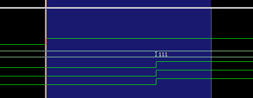
This screenshot of the waveform output in our simulation environment (more in the next section) shows what I’m talking about:
We can zoom into the rising edge of a clock to inspect signal updates occurring across delta cycles. In the expanded view (shown in blue), we focus on the first rising clock edge (marked by the yellow line), where the PWM output begins transitioning. While the signals eventually go HIGH two delta cycles after the edge, their values are still LOW at the instant of the rising edge, which is when they are sampled for synchronous logic. The key takeaway is that everything shown in the blue region happens with zero advancement in simulation time.
There’s a way to force the update without passing simulation time (wait for 0 ns), but I decided to work with the way it is instead.
Moving on, once we break out of each while loop, the assertions check if the correct number of HIGH and LOW cycles have been counted. If not, an error is reported to the simulation console. This way, we can know if our PWM is correct without manual inspection.
After the outermost loop has completed, a final report statement flagging the end of the process is executed, and the process waits indefinitely. Recall that the stimulus process continues advancing simulation time after this point.
That’s it for our testbench code! Let’s move to ModelSim and make sure it works!
Running the Testbench in ModelSim
Okay, let’s wrap up this tutorial by running our testbench in ModelSim. There are a couple of free versions of ModelSim out there. I’m using the latest free version: ModelSim – Intel FPGA Starter Edition 2020.1, Revision 2020.02, which you can download directly from Intel here (Windows and Linux only).
Start by opening ModelSim and creating a new project. Go through the prompts to add new files to the project, and make sure to add led_dimmer.vhd and led_dimmer_tb.vhd. Once the files have been added, compile the files. You should get green check marks in the status column after successful compilation.

Next, go to the Library tab, click the work library to expand it, then right-click led_dimmer_tb. You’ll be given the option to simulate. Choose that.

ModelSim will then start its internal simulation environment, and the menus might change a little before settling into a state where it’s ready to initiate the simulation. You can step through the simulation in specific time increments, but we want to run the entire simulation at once.
To simulate in its entirety, choose the menu option Run -All in the Run submenu:

The simulation will run, and when finished, you’ll see a pop-up dialog asking “Are you sure you want to finish?”. Make sure you press “No”. This will keep the simulation environment open, but the simulation will have stopped cleanly.

Now that the simulation has ended, we should see the following output in the ModelSim console (“Transcript”):
We can see the report statements indicating that the simulation completed successfully for each channel. Nice! Our self-checking testbench is a success.
It’s important to keep in mind that it took several iterations of me writing this testbench to make sure it works correctly. Just like any other code, it’s prone to errors, and just because you make report statements saying something passed a test, doesn’t mean it did! You have to verify the testbench itself. I did that through careful analysis of the waveform output against what I was doing in code in early iterations of the testbench. So, while everything is working “first try” here, in reality, we’re looking at the final polished testbench.
To inspect what’s happening further, I encourage you to add signals in the simulation to the Wave view. You can generally do this by going to the “sim” tab, selecting the instance of interest, and then, in the “Objects” menu, you can right-click a signal or constant of interest and add it to the Wave view. Remember to restart and rerun the simulation after adding signals to the Wave view.

We’ll wrap up by showing a portion of the Wave view I was working with last to give you an idea of what it can look like:

I’ve added several signals to inspect. You can add signals and variables from any module that’s been instantiated, for example, the testbench or the DUT itself. Another cool feature is that green (or red) markers appear at the top of the timeline, marking when our report statements occur. Green markers mark report statements with note severity, while red markers indicate error severity. I’ve highlighted our report statements at the end of the monitor process with a vertical yellow line in the screenshot above.
That wraps up the simulation! I encourage you to run the testbench with different parameters for the generics, explore the Wave view more, and take a closer look at delta cycles.
Conclusion
If you’ve made it this far, thanks for following the tutorial. I hope you’ve learned something new.
In this article, we:
- Designed and wrote a self-checking testbench for our LED dimmer module.
- We ran the testbench in ModelSim and ensured our module successfully passed all the checks.
- We looked at how to add signals to the Wave view.
Stay tuned for the next and final article in this series, Part 3, where we’ll write our top-level wrapper for the Arty A7-100T board, make a project in Vivado, synthesize, implement, and finally program our board.